|
Fit the pot mechanically so that the range of
motion is towards the center of the wiper and so that extremes of
travel do not cause the pot to hit either end stop.
|
When this board is to be fitted it is connected
in series with the brake pot - the plug that would connect into the
brake pot connects into this board instead, and an identical plug runs
over to the brake pot. This board is ideally mounted in a small
box
reasonably close to brake pot (but not quite close enough to be
kicked)
|
As with all electronics, this board may possibly
be susceptible to interference from electrical noise, such as brushes
on an alternator or a radio transmitter. Keeping the wiring to
the pot
short, and possibly mounting the board in a metal box, will reduce this.
|
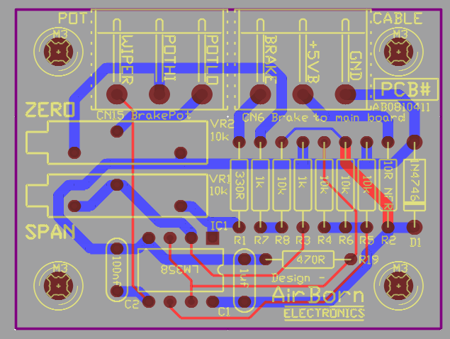
The two connectors to the board are clearly
labelled: POT and CABLE (back to the main board).
All the pot
connectors are wired up the same way, Pin 1 (the right pin as you see
it here) on all connectors is Ground, for a pot, that is connected to
the low side of the wiper. Pin 2 (the middle pin) on the pot
connector
is the "high" side of the wiper. Pin 3 (the left pin as you see
it
here) on the pot connector is the "middle" connection; the wiper itself.
|
The pot board gets its power from the main board
through the pot wiring. If there is a short, miswiring, or other
problem the board will generally still be operational, or part R2 10R
NFR will go open circuit to protect the board. Other than
protection
from moisture and kicks the board should not need any attention once
fitted.
|
To adjust, connect up the circuitry. Run a
quick check with a digital voltmeter across pins 1 (black) and 2 (red)
of CN6 - you should see +5.0V. Then connect the DVM across pins 1
(black) and 3 (red) of CN6 for the remainder of the tests.
|
With the brake pedal at the zero position,
Adjust preset VR2 ZERO until the DVM is close to, but not at,
zero. I
would aim for about 0.1V. The reason for not going completely to
zero
is that you will not know if you have gone past zero.
|
(Steves notes: At this point the voltage
across pins 1 of CN6 and pin 3 of the other connector, CN15, should be
close to 1.66V, but you shouldn't have to measure this. As you
press
the brake pedal the voltage here should go up to, but not reach 2.33V)
|
Pressing the brake pedal in should cause the
voltage seen by the DVM across pins 1 and 3 of CN6 to go up. If
it
doesn't there is likely a problem with wiring to the pot, or possibly
the zero and span adjustments are way off one end (they are in the
middle when the boards are delivered)
|
With the brake pedal fully pressed in, adjust
the SPAN preset until the DVM shows the voltage we have decided will be
our "Brake fully in" voltage. Right now, aim for 2.25V.
|
With the brake released again, adjust the ZERO
preset until the DVM shows the voltage we have decided will be our
"Brake fully out" voltage. Right now, aim for 0.25V.
|
Repeat the last two steps; because the two
adjustments can affect each other.
|
It is industry practice to put a dot of red
adhesive (either loctite or nail varnish) on the preset screw to say
"this has been adjusted" and hold it in position. However, the
presets
usually don't go moving of their own accord.
|